[Amended 1/27/97]
This Pond Code is adapted from the USDA Soil Conservation Service's Small Pond code 378. The original text is shown with a line through it so those familiar with original text can find changes and requirements specific to London Britain Township.
Definition
In this standard, ponds constructed by the first method are referred to as embankment ponds, and those constructed by the second method are referred to as excavated ponds. Ponds constructed by both the excavation and the embankment methods are classified as embankment ponds if the depth of water impound against the embankment at spillway elevation is 3 feet or more. The depth of water impounded is designed as the difference between the spillway inlet elevation and channel elevation at the point of discharge.
Purpose
To provide water for livestock, fish and wildlife, recreation, fire control, crop and orchard spraying and other related uses and to maintain or improve water quality. This standard also applied to stormwater management ponds that are not within the scope of SCE Technical Release No. 60.
Scope
This standard establishes the minimum acceptable quality for the design and construction of ponds if.
1. Failure of the dam will not result in loss of life: in damage to homes, commercial or industrial buildings, main highways, or railroads; or in interruption of the use of survive of public utilities.
2. The product of the storage times the effective height of the dam is less than 3,000. Storage is the volume in acre-feet in the reservoir below the elevation of the crest of the emergency spillway. The effective height of the dam is the difference in elevation in feet between the emergency spillway crest and the lowest point in the cross section taken along the centerline of the dam. IF there is no emergency spillway, the top of the darn is the upper limit.
3. The effective height of the dam is 35 feet or less and the dam is hazard class.
4. Dams that exceed the scope of this standard shall be designed and constructed to meet the requirements of SCS Technical Release No. 60.
Conditions where practice applies
Site conditions.
Site conditions shall be such that runoff from the design storm can be safely passed through
1. a natural or constructed emergency spillway,
2. a combination of a principal spillway and an emergency spillway or
3. a principal spillway.
Drainage Area
The drainage area above the pond must be protected against erosion to the extent that expected sedimentation will not shored the planned effective of life o the structure. The drainage area shall be large enough so that surface runoff and groundwater flow will maintain an adequate supply of water in the pond. The quality shall be suitable for the water's intended use.
Reservoir Area
The topography and soils of the site shall permit storage of water at a depth and volume that ensure a dependable supply, considering beneficial use, sedimentation, season of use, and evaporation and seepage losses. If surface runoff is the primary source of water for a pond, the soils shall be impervious enough to prevent excessive seepage losses of shall be of a type that sealing is practicable. The sediment storage volume shall be no less than the expected sediment accumulation during a period equal to the design life.
Planning Considerations
Water Quantity
1. Effects upon components of the water budget, especially effects on volumes and rates of runoff, infiltration, evaporation, transpiration, deep percolation and groundwater recharge. The drainage area for wet ponds should be at least four (4) acres for each acre- foot of water. These requirements may be reduced if a dependable source of groundwater or diverted surface water contributes to the pond.
2. Variability of effects caused by seasonal or climatic changes.
3 . Effects on the downstream flows or aquifers that could affect other water uses or users.
4. Potential for multiple use.
5. Effects on the volume of downstream flow to prohibit undesirable environmental, social or economic effects.
Water Quality
1. Effects on erosion and the movement of sediment pathogens and soluble and sediment attached substances that are carried by runoff.
2. Effects on the visual quality on onsite and downstream water resources.
3. Short-term and construction related effects of this practice on the quality of downstream water courses.
4. Effects of water level control on the temperature of downstream water to prevent undesired effects on the aquatic and wildlife communities.
5. Effects on wetlands and water-related wildlife habitats.
6. Effects of water levels on soil nutrient processes such as plant nitrogen use or denitrification.
7. Effects of soil water level control on the salinity of soils, soil water, or downstream water.
8. Potential for earth moving to uncover or redistribute toxic materials such as Wine soils.
Design criteria for embankment ponds
Foundation
Foundation Cutoff
Seepage Control
Seepage control is to be included if
1. pervious layers are not intercepted the cutoff,
2. seepage creates swamping downstream,
3. such control is needed to ensure a stable embankment, or
4. special problems require drainage for a stable dam.
Seepage may be controlled by
1. foundation, abutment, or embankment drains
2. reservoir blanketing; or
3. a combination of these measures.
Earth Embankment
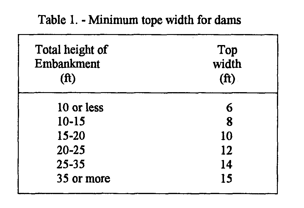
The minimum top width for a dam is shown in Table 1. If the embankment top is to be used as a public road the minimum width shall be 16 feet for one-way traffic and 25 feet for two-way traffic. Guardrails or other safety measures shall be used where necessary and shall meet the requirements of the responsible road authority.
The combined upstream and downstream side slopes of the sealed embankments shall be no less than five horizontal to one vertical and neither slope shall be steeper than two horizontal to be vertical. All slopes must be designed to be stable.

The floor of the pond shall be graded as flat as possible to permit uniform ponding. Side slopes leading to the floor should be no steeper than three horizontal to one vertical. Approximately one foot below the normal pool elevation, a ten-foot level bench shall be provided.
Pond slopes above the normal pool elevation also shall be no steeper than three horizontal to one vertical and a reverse slope bench, at least ten feet wide must be provided approximately one foot above the normal pool elevation.
If needed to protect the slopes of the dam, special measures, such as berms, rock riprap, sand- gravel, soil cement, or special vegetation, shall be provided (Technical Releases 56 and 69)
The minimum elevation of the top of the settled embankment shall be I foot above the water surface in the reservoir with the emergency spillway flowing at design depth. The minimum difference in elevation between the crest of the emergency spillways and the settled top of the dam shall be 2 feet for all darns having more than a 20-acre drainage area or more than 20 feet in effective height.
The design height of the darn shall be increased by the amount needed to ensure that after settlement the height of the dam equal or exceeds the design height. This increase shall be no less than 5 percent, except where detailed soil testing and laboratory analyses show that a lesser amount is adequate.
Principal spillway
The crest elevation of the principal spillway for all stormwater management ponds shall be no less than one foot below the crest of the emergency spillway.
When design discharge of the principal spillway is considered in calculating peak outflow through the emergency spillway. The crest elevation of the inlet shall be such that the full flow will be generated in the conduit before there is discharge through the emergency spillway. The inlets and outlets shall be designed to function satisfactorily for the full range of flow and hydraulic head anticipated.
The capacity of the pipe conduit shall be adequate to discharge long-duration continuous, or frequent flows without flow through the emergency spillways. See Table 4 for additional requirements. The diameter of the pipe shall be no less than 4 in. If the pipe conduit diameter is 10 in or greater, its design discharge may be considered when calculation the peal outflow rate through the emergency spillway. Runoff rates and volumes shall be determined using one or more the following reference.
1. SCS Engineering Field Manual
2. SCS national Engineering Handbook, Section 4, "Hydrology"
3. SCS Technical Release 55, "Urban Hydrology for Small Watersheds"
4. SCS Technical Release 20, "Computer Program for Project Formulation"
Pipe conduits under or through the darn shall meet the following requirements. The pipe shall be capable of withstanding external loading without yielding, buckling, or cracking. Flexible pipe strength shall be not less than that necessary to support the design load with a maximum of 5 percent deflection. The inlets and outlets shall be structurally sound and made of materials comparable with those of the pipe. All pipe joints shall be made watertight by use of couplings, gaskets, caulking, or by welding.
For dams 20 ft or less in effective height, acceptable pipe materials are cast-iron, steel, corrugated steel or aluminum, asbestos-cement, concrete, plastic, vitrified clay with rubber gaskets. Asbestoscement, concrete and vitrified clay pipe shall be laid in a concrete bedding. Plastic pipe that will be exposed to direct sunlight shall be made of ultraviolet-resistant materials and protected by coating or shielding, or provisions for replacement should be made as necessary. Connection of plastic pipe to less flexible pipe or structures must be designed to avoid stress concentrations that could rupture the plastic.
For dams more than 20 ft in effective height, conduits shall be plastic, reinforced concrete, cast- inplace reinforced concrete, corrugated steel or aluminum, or welded steel pipe. The maximum height of fill over any principal spillway steel or aluminum pipe must not exceed 25 ft. Pipe shall be watertight. The joints between sections of pipe shall be designed to remain watertight after joint elongation caused by foundation consolidation. Concrete pipe shall have concrete bedding or a concrete cradle, if required. Cantilever outlet sections, if used, shall be designed to withstand the cantilever load. Pipe supports shall be provided when needed. Other suitable device, such as a Saint Anthony Falls stilling basin or an impact basin may to used to provide a safe outlet.
Protective coatings of asbestos-bonded, asphalt coated, or vinyl coating on galvanized corrugated metal pipe, or coal tar enamel on welded steel pipe should be provided in areas that have a history of pipe corrosion, or where the saturated soil resistivity is less that 4,000 ohms-cm, or where soil pH is lower than 5.
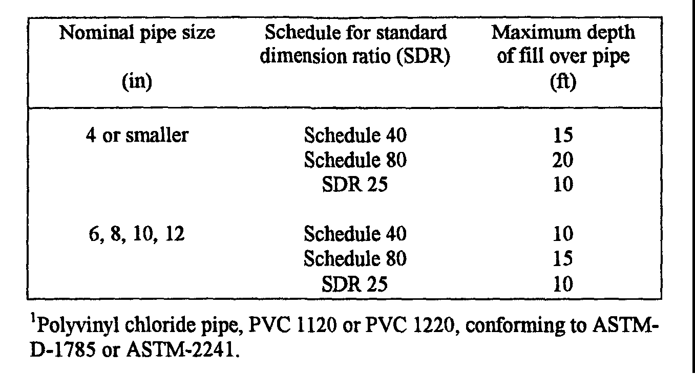
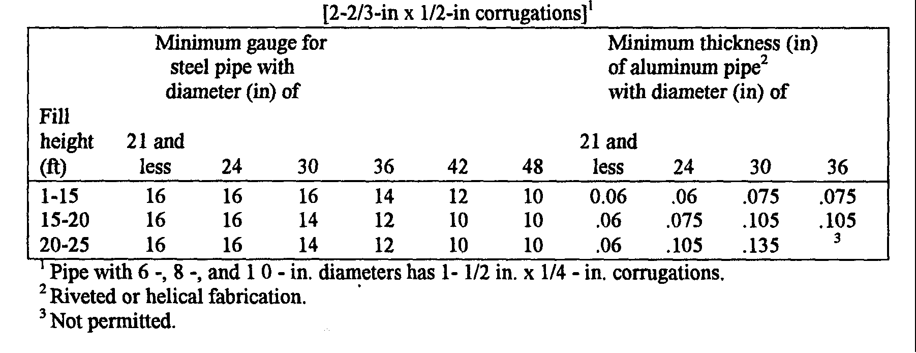
Specifications in tables 2 and 3 are to followed for polyvinyl chloride (PVC) steel, and aluminum pipe.
Cathodic protection is to be provided for coated welded steel and galvanized corrugated metal pipe where soil and resistivity studies indicate that the pipe needs a protective coating, and where the. need and importance of the structure warrant additional protection and longevity. If cathodic protections is not provided for in the original design and installation, electrical continuity in the form of jointbridging straps should be considered on pipes that have protective coatings. Cathodic protection should be added later if monitoring indicates the nee&
Practice standard 430-FF provides criteria for cathodic protection of welded steel pipe.
Seepage control along a pipe conduit spillway shall be provided. Anti-seep collars shall be installed around all conduits through earth fills according to the following criteria.
1. Sufficient collars shall be placed to increase the seepage, length along the conduit by a minimum of 15 percent of the pipe length located within the saturation zone.
2. The normal saturation zone shall be determined by projecting a line at a slope of four horizontal to one vertical from the point where the normal water meets the upstream slope to a point where this line intersects the invert of the pipe conduit.
3. Maximum collar spacing shall be 14 times the minimum projection above the pipe. The minimum collar spacing shall be 5 times the minimum projection.
4. Anti -seep collars should be placed within the saturated zone. In cases where the spacing limit will not allow this, at least one collar will be in the saturated zone.
5. All anti-seep collars and their connections to the conduit shall be watertight and made of material compatible with the conduit.
6. Collar dimensions shall extend a minimum of two feet in a directions around the pipe.
Table 2-Acceptable PVC pipe for use in earth dams'

Table 3. -Minimum gauge for corrugated metal pipe
