
Inlets and manholes shall be constructed where required in accordance with the requirements of the Standard Specifications and Standard Construction Details.�
a. All street inlets shall be New Jersey Department of Transportation Standard Type B. Casting heights on any streets shall be two inches (2") greater than the specified curb face and the gutter shall be properly transitioned approximately ten feet (10') on either side of the inlet.�
b. All yard inlets shall be Standard Type A or E.�
c. Combination drains shall be installed where the character and composition of the earth in the roadbed itself or adjacent terrain renders such installation necessary.�
1. These combination drains shall be constructed as follows: The bottom one third (1/3) of the pipe shall be caulked with jute or equivalent material and the pipe shall be laid in a stone bed for a depth equal to one-half (1/2) the diameter of the pipe.�
2. The trench shall then be filled in the same manner as described in Section 25-1700.32.2g above.�
d. In continuous conduit runs, spacing between structures (inlets or manholes) shall not exceed six hundred feet (600').�
e. Structures (inlets or manholes) shall be located so as not to interfere with primary routes of pedestrian travel or any proposed handicapped ramp or similar facility.�
f. In general, surface flow length, for flows of four or more cubic feet per second, on paved surfaces shall not exceed seven hundred fifty feet (750'), provided that:�
1. Gutter flow widths on local and local collector streets shall not exceed eleven feet (11'), or such narrower width as may be necessary to provide a twelve foot (12') wide clear lane in the center of the roadway.�
2. Gutter flow widths on collector streets shall not exceed nine feet (9'), or such narrower width as may be necessary to provide two (2) twelve foot (12') wide clear lanes in the center of the roadway.�
3. Gutter flow widths on major collector streets without shoulders shall not exceed five feet (5'), or such narrower width as may be necessary to provide four (4) ten foot (10') wide clear lanes in the center of the roadway.�
4. Gutter flow widths on minor and principal arterial streets and major collector streets with shoulders shall be retained within the shoulder areas.�
5. Swale gutter flow widths in parking areas shall not exceed twelve feet (12').�
6. Gutter flow widths shall provide for the maintenance of two (2) ten foot (10') wide clear lanes in all access and major circulation drives and one twelve foot (12') wide clear lane in all other aisles in all parking areas, except as otherwise provided in Section 25-1700.22.�
g. Maximum design capacities which may be used to determine actual inlet location spacing are:�
1. Not in Sump Conditions:�
Type B 4 cubic feet per second�
Type E (in paved areas) 4 cubic feet per second�
Type E (in yard areas) 1.5 cubic feet per second�
2. In Sump Conditions:�
To be individually designed�
h. Only Type B inlets shall be used in curbed roadways or curbed access or major circulation drives.�
i. Generally, sufficient inlets will be placed to eliminate any flow exceeding two (2) cubic feet per second across any intersections.�
j. Parking areas may be designed to allow ponding in order to decrease intensity of runoff. In such case, ponding will not be allowed in any access or major circulation drive or in any area of heavy pedestrian activity and shall not exceed six inches (6") at any point calculated for the appropriate design storm in accordance with Section 25-1700.33.�
Open channels shall be designed to contain the required flow and shall have a design velocity low enough in the judgment of the City Engineer, to prevent erosion.�
a. The minimum easement for open channel sections shall be the maximum design top width of the channel section segment plus twenty-five feet (25') rounded to the next highest five foot (5') increment.�
1. The excess easement area shall be provided offset to that side of the channel most convenient for use by maintenance crews.�
2. The minimum distance between the channel top edge and any easement line shall be five feet.�
b. Excess velocity, if any, as determined by the City Engineer, in open channels must be controlled by sod, rip-rap, paving, ditch checks, or other suitable methods.�
c. Changes of direction in open channels must have a maximum radius of eight hundred feet (800') or be adequately paved or rip-rapped.�
d. Generally, unlined open channel cross-sections shall have side slopes not steeper than four to one (4:1) for channel depths of two (2) feet or less and not steeper than eight to one (8:1) for channel depths of more than two feet (2'). Line open channel side slopes shall not be steeper than two to one (2:1).�
e. The bottoms of all unlined open channels and the channel side slopes, to at least the design flow level, will be sodded with suitable coarse grass sod.�
f. All unlined open channel side slopes above the design minimum flow level will be topsoiled and seeded or otherwise suitably stabilized in accordance with an approved soil disturbance permit.�
g. All unlined open channels which can be expected to have a base flow of five (5) cubic feet per second or more for at least two (2) out of every twelve (12) months will be provided with a low flow channel using gabions, riprap, lining, one-third (1/3) pipe sections, or other arrangements approved as part of the final plat submission.�
Culverts or drains shall be constructed as specified herein.�
a. The location, length, depth, grade, type, and size of pipe shall be designated on the plans indicated herein except where unusual or exceptional soil or other conditions are discovered at the time of construction, which are not provided for in the plans, in which case such construction shall be determined by the City Engineer.�
b. Trenches shall be bridged at the street crossings, intersecting streets, public and private entrances in such a manner that traffic will not be interrupted.�
c. The contractor shall have a sufficient quantity of timber and equipment constantly on hand for planking, sheet piling, fencing or shoring, and adequate pumping apparatus to meet all requirements of construction for use in case of accident or emergency.�
d. All trenches for culverts, drains or french drains shall be excavated at least nine inches (9") and not more than thirty inches (30") wider than external diameter of the pipe to be used therein.�
e. The pipe shall be laid on a firm bed and the bottom of the trench shall be excavated to the line and grade given or directed by the City Engineer.�
1. The bottom of the excavation shall have the shape and dimensions of the lower half of the pipe.�
2. When rock or rubble is encountered and removed from the trench as specified, this excess depth shall be refilled with suitable materials and tamped thoroughly.�
f. The pipe shall be laid and all joints shall be treated as determined by the City Engineer.�
g. The filling around the pipe shall be made in layers with approved materials free from rock, and each layer shall be tamped thoroughly around and over the pipe.�
�
h. Where indicated or directed, old pipe or insufficient sized culverts shall be removed and relaid, extended or renewed in the same manner as specified above for new pipe culverts or drains.�
i. Easement of a width sufficient to allow proper maintenance but in no case less than fifteen feet (15'), shall be provided for the outletting of all drains, pipelines, etc. to streams, existing storm drains, or other legal drainage courses. These easements shall be granted to the City in writing, subject to the approval of the City Attorney.�
j. All non-pipe culverts shall be designed for AASHO H20-44 loading.�
1. All culverts of any type shall be carried to the roadway right-of-way and shall terminate with headwalls or other approved end treatment.�
2. All conduits terminating or beginning in open channels shall be provided with headwalls or other appropriate end treatment.�
Headwalls shall be provided at all terminations. These shall be poured concrete headwalls, precast concrete end sections or corrugated metal end sections in accordance with the approved final plan. Poured concrete headwalls shall be wing-type headwalls with aprons in accordance with the Standard Construction Details.�
Retaining walls installed in slope control areas shall be constructed of heavy creosote timber or logs, or reinforced concrete, other reinforced masonry or of other acceptable construction and adequately designed to carry all earth pressures including any surcharges. The heights of the retaining walls should not exceed one-half (1/2) of the horizontal distance from the foundation wall of any building to the face of the retaining wall . �
Guardrails and/or railings shall be placed at all drainage structures where the interests of pedestrian or vehicular safety would dictate.�
a. The Planning Board may require that any open channel, other than naturally occurring streams, be fenced with chain link fencing forty-eight inches (48") high if the banks of the channel are steeper than one (1') foot vertically for every four (4') feet horizontally and either the total depth of the channel exceeds four feet (4') or the channel would be expected to have a depth of flow greater than two feet (2') more often than once every ten (10) years.�
b. For maintenance purposes, gates may be required by the Planning Board at approximately two hundred foot (200') intervals.�
The developer shall take all necessary precautions to prevent any siltation of streams during the construction of the site.�
a. If required by the Planning Board as a condition of approval or by the Planning Board Engineer during construction, the developer shall provide adequate provisions to prevent all deposits of silt or other eroding material in any stream or water course.�
b. Such provisions may include, but not limited to construction and maintenance of siltation basins or holding ponds throughout the course of construction.�
c. The use of siltation and oil separation basins with controlled outflows will be required to prevent pollution of waterways when discharge is into a lagoon, bay or other standing body of water.�
All drainage arrangements (either piped or overland flow) for sites on County roads or State highways shall be approved by the County Engineer or the New Jersey Department of Transportation, respectively, in addition to being acceptable to the Planning Board.�
a. The existing system of natural drainage within each development shall be reserved to the maximum extent possible. To this end, the Planning Board may require the preservation of natural drainage swales, recharge areas, wet weather ponds and similar features and may require suitable drainage and conservation easements and possible increases in lot size to allow usable lots with the preservation of such features.�
b. Subject to review and approval by the Planning Board, the design of the development may be modified to take advantage of the natural drainage features of the land. In such review, the Planning Board will use the following criteria:�
1. The utilization of the natural drainage system to the fullest extent possible.�
2. The maintenance of the natural drainage system as much as possible in its unimproved state.�
3. When drainage channels are required, wide shallow swales with natural vegetation will be preferred to other sections.�
4. The construction of flow retarding devices, detention areas and recharge berms to minimize runoff value increases.�
5. Maintenance of the base flow in streams, reservoirs and ponds.�
6. The reinforcement, improvement, and/or extension of the natural drainage system to such an extent as is necessary to eliminate flooding and excess maintenance requirements.�
a. For closed conduits, the design criteria shall be a two (2) year storm frequency as a minimum when not immediately adjacent to the discharge end of the system. When a development's conduit system is located adjacent to the discharge point a five (5) year storm frequency shall be used.�
b. For open channels ten (10) years.�
c. For detention facilities, a twenty-four (24) hour flood with a return period not less than fifty (50) years.�
d. For retention facilities, double the capacity obtained by applying the requirements for detention facilities.�
e. For gutter flow calculations, five (5) years.�
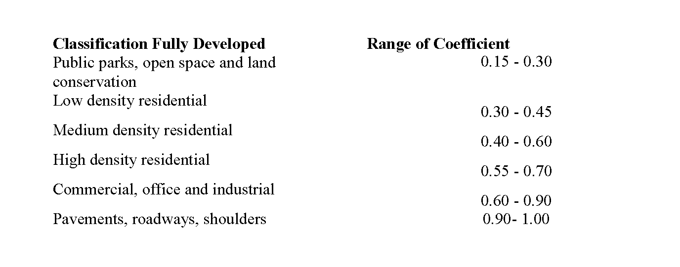
Runoff determinations should be made using the rational formula or, in unusual cases, other methods with the prior approval of the City Engineer. Upstream areas should be considered based on their full development potential according to current zoning or the current use, whichever produces the greatest runoff. Runoff coefficients used should generally fall in the following ranges:�
In general, velocities in closed conduits at design flow should be at least two and five-tenths feet (2.5') per second, but not more than the velocity which will cause erosion damage to the conduit and velocities in open channels at design flow shall not be less than one and five-tenths feet (1.5') per second and not greater than that velocity which will begin to cause erosion or scouring of the channel.�
a. For unlined earth channels, the maximum velocity allowed will be two feet (2') per second. For other channels sufficient design data and soil tests to determine the character of the channel shall be made to developer and shall be made available to the City Engineer at the time of drainage review.�
b. At transitions between closed conduits and open channels or different types of open channels suitable provisions must be made to accommodate the velocity transitions. These provisions may include riprapping, gabions, lining, aprons, chutes and checks, or others, all suitably detailed and approved as part of the final plat submission.�
c. For all flow of forty (40) cubic feet per second or more, tailwater depth and velocity calculations shall be submitted.�
In general, the Manning formula will be used by the City Engineer to review the adequacy of proposed drainage facilities. Other formulae may be used in particular cases with the previous agreement of the Board.�
All drainage facilities carrying runoff from tributary areas larger than one-half (1/2) square mile must have the approval of the New Jersey Department of Environmental Protection, Division of Water Resources. Evidence of such approval shall be required to be submitted prior to the final approval of the site plan.�
All encroachments of natural waterways must be referred to the New Jersey Department of Environmental Protection, Division of Water Resources for approval in accordance with statute. The State may retain jurisdiction in which case a permit will be necessary as set forth above or may refer the matter to the County Engineer for review.�
Storm drainage systems shall be designed to include not only the proper drainage of the actual area of the specific development and the area tributary thereto, but shall also include the disposal of the storm water runoff to an adequate outlet or other means of final disposal of the storm water, such as a river, running stream, lagoon or an existing adequate storm sewer.�

